

How To Adjust The Tps Sensor
How To Adapt the Throttle Position Sensor
Past Chuck Westbrook
Tools Needed
(1) A high impedance voltmeter (preferably a digital) with one alligator clip.
(2) A small safe pivot opened upwards to form a 90 degree angle.
(3) Depending on the blazon of fasteners that hold your TPS in place; the tools needed to loosen and retighten them. Mine had bolts with a combination Philips screw driver and 7MM nut caput. Some take only a screwdriver caput and need a xc caste bend screwdriver or screw driver tips for a ratchet drive. These spiral driver head only bolts are the pits and most owners take replaced them later on removing the throttle body. Make sure your engine ground points are clean and tight. An boosted grounding strap for the throttle body or extension manifold to the firewall is a adept thought to proceed your engine'south electrons flowing freely.
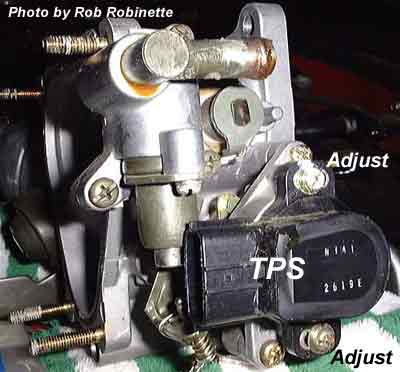
The throttle-trunk, firewall side with TPS
TPS Connector Leads (4 lined up vertically) and Required Voltages:
(i) second from top (green wire with red stripe), this goes to the 3F ECU connector. Closed throttle +V range is 0.75 to one.25. Fully opened throttle +Five range is 4.8 to 5.0.
(2) Lesser (black wire with green stripe), this goes to the 3G ECU connector. Closed throttle +V range is 0.1 to 0.seven. Fully opened throttle +V range is 4.2 to four.six.
Procedures
(1) Start and run engine until at normal operating temperature and the fast idle cam is at normal idle position.
(2) Plough off the engine.
(3) Remove the AWS hose that connects to the throttle body curved inlet pipe and to the AWS solenoid behind the throttle
torso. This is to give you easier access to the TPS bolts.
(4) Remove the hose from the pressure sensor on the firewall and tuck it down out of the way. This also gives y'all more than
room to admission the TPS bolts. If extra room is even so needed, remove the pressure sensor from the firewall.
(5) Totally loosen the bottom TPS commodities and partially the top one.
(vi) Connect the negative volt meter lead to a good ground indicate. I used one in the diagnostic connector since it goes to the ECU.
(7) Insert the condom pivot point into the TPS 3F or 3G connector (meet in a higher place) betwixt the safe atmospheric condition seal and the wire. Using the alligator clip, attach the positive voltmeter lead to the safe pivot head. Select the advisable voltmeter range. Exist sure non to accidentally ground this pb!
(8) Turn the ignition on without starting the engine. If there isn't a voltmeter reading, suit the prophylactic pin until it does have a reading.
(nine) Tape the voltages for closed and fully opened. Open the throttle fully by hand, not the accelerator pedal.
(9a) Verify that the voltages increase as the throttle is opened. Look for "dead" spots or voltage fluctuations as you slowly open up the throttle.
(10) Do the same for the other TPS connector point.
(11) If any of the four voltages are out of range, loosen the top TPS commodities and suit the TPS until all four are in range. If all 4 can't be adapted correctly; so either the TPS is bad, the fast idle cam is still engaged, or the idle gear up screw on the throttle is way off normal position.
The post-obit note is for PFS PMC users only
Notation: The further the idle fix screw on the throttle is adjusted down (throttle opens up), the college the depression stop readings volition be if the loftier ends are good. That'southward considering the arc of throttle movement volition exist shifted towards the loftier end. Try and imagine the geometry of the throttle rotating shaft connected to the TPS which is zilch only twin variable resistors like a volume control on a stereo. Fifty-fifty though I had all four in their voltage ranges, my PMC would non read WOT. I adjusted the TPS only until WOT occurred, and then rechecked the four voltages. They were withal good but shifted towards the loftier end of their ranges. WOT is only needed for vent learn. My 3K stumble wasn't bad until forcing my TPS to prove WOT on the PMC, then information technology got worse!
(11a) Adjust your throttle linkage to insure that you also become WOT from your accelerator pedal. I had to also do this.
(12) Tighten up the TPS bolts, verify the voltages are withal within range and put everything dorsum together.
Drive the car a lilliputian, then readjust your idle air bleed screw if needed.
Chuck Westbrook
Source: https://robrobinette.com/tps_adj.htm
0 Response to "How To Adjust The Tps Sensor"
Post a Comment